How to run using scripts
This document describes the overall workflow for how to setup and run a rollover simulation.
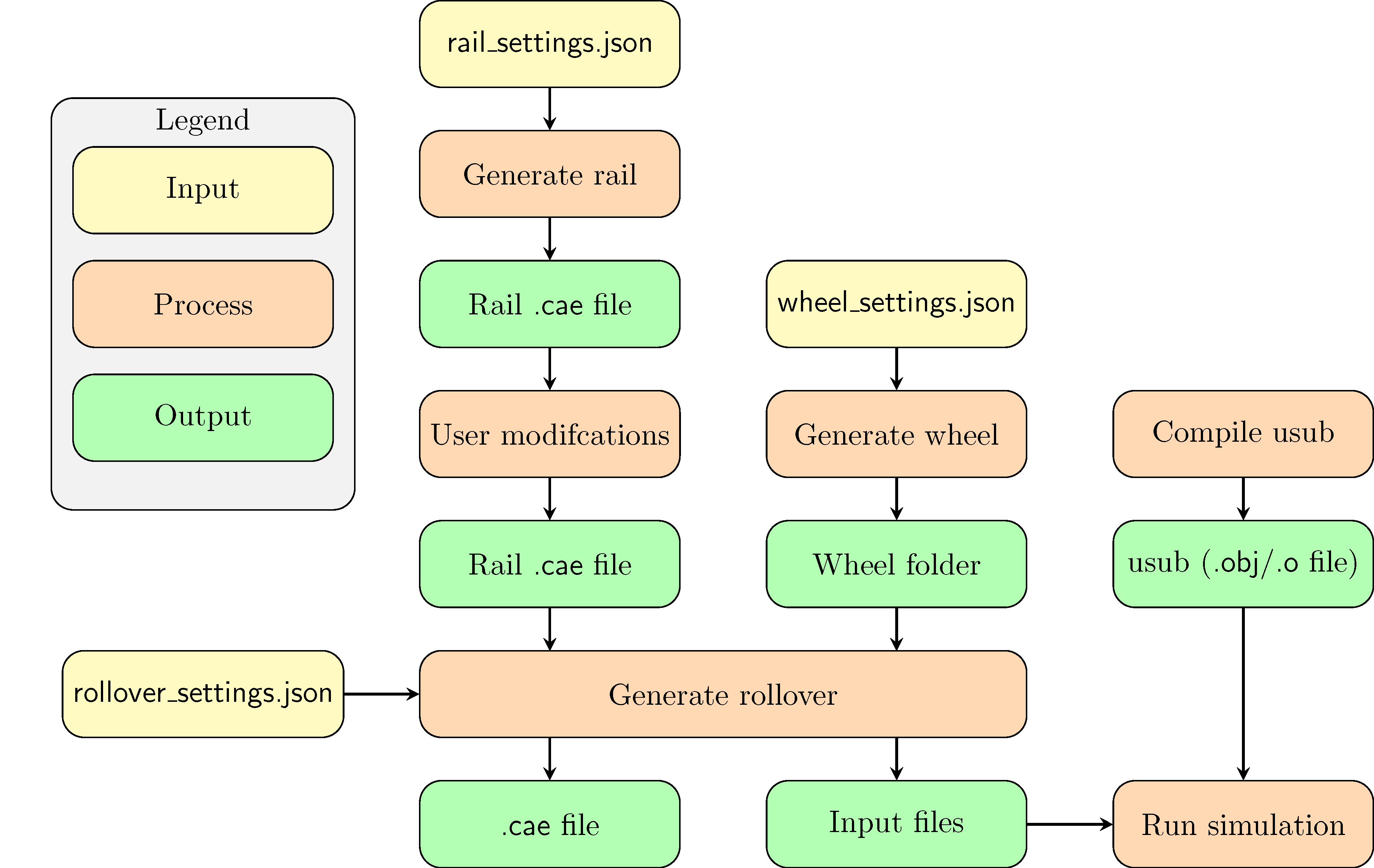
The rollover simulation consists of an elastic wheel rolling over a rail. To apply the “wormhole” boundary condition for the wheel, a set of user subroutines (usub) are used. So in order to setup and run the simulation, the user must do the following steps
Create the rail (“Rail
.caefile”)Create the wheel (“Wheel folder”)
Compile user subroutines (“usub (
.obj/.ofile)”). Normally not required each timeCreate the rollover simulation (“Input files”)
Most of the scripts rely on a .json formatted settings file, for
further details on this format see The json format.
Create the rail
The rail is (typically) created by first calling the
create_rail_3d.py abaqus script (see Create a basic rail). This
creates a .cae file. This file can then be edited to adapt to the
specific simulation (see Modifying the basic rail). The end product
will be a .cae file that may be convenient to store
in the data/rails folder in the repository
(see The data folder and how to specify paths).
Create a basic rail
A basic rail is created by calling the abaqus script create_rail_3d.py from a folder containing a file rail_settings.json This file should contain the following settings:
"material"(optional): Describes the material model and parameters to be applied to the entire rail. See Material specification. If not given, an elastic material will be set."rail_profile"(mandatory): Path to an Abaqus sketch, saved as a.satfile, describing the profile of the rail in the xy-plane. See Creating a profile sketch for further details."rail_length"(mandatory): The length (z) of the rail to be created"rail_name"(mandatory): The name of the.caefile to be created"refine_region"(optional):[[xmin, ymin], [xmax, ymax]]Describes a rectangle within which the fine mesh will be applied and from which the contact surface will be defined. If not given, the entire rail will be finely meshed, and the entire surface will be set as contact surface."fine_mesh"(mandatory): The element size for the fine mesh"coarse_mesh"(mandatory): The element size for the coarse mesh."sym_dir"(optional): The direction of the symmetry plane. If not given, no symmetry is assumed. If given, should be[1,0,0]or[-1,0,0].
Material specification
The material specification should contain the following settings:
"material_model": Name of the material model to use"mpar": Material parameters, given with new keywords.
The supported material models are described below. Note, however, that
after the rail .cae file has been created, you can freely edit the
material model specification.
elastic
"material_model": "elastic"
"mpar": {"E": <Elastic modulus>, "nu": <Poissons ratio>}
chaboche
"material_model": "chaboche",
"mpar": {"E": <Elastic modulus>, "nu": <Poissons ratio>,
         "Y0": <Initial yield>, "Qinf": <Isotropic saturation>,
         "biso": <Isotropic hardening rate>,
         "Cmod": [<Kinematic modulus 1>, ..., <Kinematic modulus N>],
         "gamma": [<Kinematic saturation speed 1>, ...,
                   <Kinematic saturation speed N>]
        }
user
"material_model": "user",
"mpar": {"user_mpar_array": [<param 1>, ..., <param N>],
         "nstatv": <num_state_variables>
        }
Modifying the basic rail
To script all details of how the rail should be meshed, and if there should be inclusions, cracks, etc. is rather cumbersome and not time efficient. Therefore, it is chosen to allow the user to edit the rail part as an intermediate step. In general, creating the basic rail above is not necessary, but highly recommended as it ensures that correct names are given to sets and surfaces. When modifying the rail part, it is therefore important not to change set names etc. With large geometric modifications, it might also be necessary to redefine these sets to capture the correct parts. A summary of the requirements for the rail part that is used later when generating the rollover is given here.
The model should be named “RAIL”
The part should be named “RAIL”
Sets
“BOTTOM_NODES” should contain all nodes at the bottom of the rail
“SIDE1_SET” should contain all nodes on the face at z=0
“SIDE2_SET” should contain all nodes on the face at z=L where L is the length of the rail.
“RAIL_CONTACT_SET” should contain the face where potential contact with the wheel can occur.
If present, “SYMMETRY” should contain all nodes on the symmetry face at x=0
Surfaces
“RAIL_CONTACT_SURFACE” should be the surface where potential contact with the wheel can occur.
Mesh
The rail must be meshed, and no constraints should be added (i.e. one cannot use incompatible meshes because this introduces constraints between the nodes).
The mesh in “SIDE1_SET” and “SIDE2_SET” must match. I.e. the mesh in “SIDE2_SET” should be a translation from the mesh in “SIDE1_SET”.
Sections, including material definitions, must be defined on cells of the part.
When working with TET elements, the script
make_rail_mesh_symmetric.py can be used to ensure a periodic mesh.
Otherwise, if HEX meshes are used as a mapped mesh, this will also give
the same mesh on both sides.
Create the wheel
A wheel super element is created by calling the abaqus script create_wheel_3d.py from a folder containing a file rail_settings.json This file should contain the following settings:
"wheel_name"(mandatory): Name of the folder where the wheel data are placed"wheel_angles"(mandatory):[min_ang, max_ang], the angular interval containing the retained wheel nodes. Wrt. the negative y-axis, positive rotation around the x-axis. In radians."wheel_profile"(mandatory): Path to an Abaqus sketch, saved as a.satfile, describing the profile of the wheel in the xy-plane. See Creating a profile sketch for further details."mesh_sizes"(mandatory):[fine, coarse], the fine and coarse mesh sizes for the wheel."wheel_contact_pos"(mandatory):[xmin, xmax], the x-interval for the part of the wheel that will be in contact with the rail. This will describe which nodes will be retained, along with"wheel_angles"."partition_line"(mandatory): y-coordinate (in the sketch) for the line outside which the wheel mesh will use the fine mesh size."quadratic_order"(mandatory): Should linear or quadratic wheel elements be used (trueorfalse)
The created wheel folder can conveniently be placed in the data/wheels directory in the repository (see The data folder and how to specify paths).
Compile user subroutines
The python script create_usub.py (in the scripts_py folder) is used to compile the user subroutines. To compile the default subroutine, run this script without any arguments.
If you have additional user subroutines that you wish to use,
give the path to the fortran source file (<your_subroutines_file>)
for these subroutines.
You can use include statements as long as all source files
reside in the same folder (or subfolders) as the main file.
In general, the subroutines should compile with
abaqus make library=<your_subroutines_file> from their
specific folders.
The result will be (1) a folder tmp_src_dir and (2) a file usubs_combined-std.o/usubs_combined-std.obj (Windows/Linux) The tmp_src_dir will contain all sources and a log file describing the compilation process (in case you have any issues). If it works successfully, you can delete this folder. The usubs_combined-std file should be copied (and probably renamed to a more descriptive name). It can be convenient to put it in the data/usubs directory in the repository (see The data folder and how to specify paths).
Create the rollover simulation
A rollover simulation is created by running the Abaqus script
create_rollover_3d.py.
It reads in the file rollover_settings.json which should contain
the following settings:
"rail"model_file: Path to the rail.caefile to useshadow_extents:[ext_at_z=0, ext_at_z=L]How far out to create shadow regions in each end of the rail.use_rail_rp: Boolean if rail reference point should be used or not.
"wheel""folder: Path to the folder describing the wheel super element"translation": How to translate the wheel (this depends on both the rail and wheel geometry. Typically, the wheel origin is in the wheel center and the rail origin is at the bottom of the rail."stiffness": The stiffness (elastic modulus) of the wheel. Its Poissons ratio is fixed at 0.3 from the wheel generation."symmetric"(optional): Should symmetry in the yz-plane be applied, defaults tofalse.
"loading""initial_depression": Amount of displacement controlled depression before changing to force control on the normal load."inbetween_step_time": Step time to use for the dummy steps (the initial depression, first loading, moving back, reapply load, and release nodes)"inbetween_max_incr": Max allowed increments during the dummy steps. To do it in a single increment is always attempted, except for the initial depression and first loading wheremin(5, inbetween_max_incr)steps are used."rolling_length": The rolling length (must be equal to rail length!)."rolling_radius": The effective rolling radius (used to convert slip to wheel rotation)."max_incr": Max number of increments to use during rolling."min_incr": Minimum (and initial) number of increments during rolling."num_cycles": Number of rollover cycles to calculate (see also Adding rolling cycles)."cycles":[1, c_spec_2, ..., c_spec_N], for which cycles that loading parameters are changed. See also Specifying load parameters."vertical_load":[F_1, F_2, ..., F_N]Amount of force pushing the wheel onto the rail."speed":[v_1, v_2, ..., v_N]The speed at which the wheel is rolling over the rail."slip":[s_1, s_2, ...., s_N]The amount of slip as the wheel rolls over the rail."rail_ext":[e_1, e_2, ..., e_N]The rail extension at the end of the cycle
"field_output"*"<field_output_1>": See Field output description *"<field_output_2>"
Specifying load parameters
All load parameters, "cycles", "vertical_load", "speed",
"slip", "rail_ext" are specified as lists with equal length.
The "cycles" list describe at which cycles the load parameters in
the other categories shall be applied. If no specific setting exists for
a given cycle, the values from the previous cycle are used. Hence, the
minimum requirement is to specify for the first cycle, and then this
will be used for all subsequent cycles.
The "slip" = \(s\) is defined such that
where \(\dot{\phi}\) is the wheel rotation speed, \(v\) is
the linear wheel velocity ("speed") and \(R\) is the wheel
radius ("rolling_radius").
Field output description
The key under "field_output" gives the name of the specific
field output request created, e.g. "<field_output_1>".
And for each of these keys the following keys should be specified:
"set": The set in the rail part for which the output should be saved. Note that there are two special names: *"FULL_MODEL": All parts of the model (wheel and rail) *"WHEEL_RP": The wheel reference point."var":["VAR_1", "VAR_2", ..., "VAR_N"]. The variables to be saved. Supported variables can be found when creating field outputs in Abaqus CAE. But typical examples are “U” (displacements and rotations), “S” (stresses)freq: How many increments between each time the variables should be saved in the active steps of the field output request.cycles: How many cycles between each time the variables should be saved (i.e. between the active steps of the field output request). If e.g. 25 is specified, output will occur on cycle 1, 26, 51, etc.